

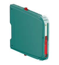
SMART Universal Barrier HiC2441
- 1-channel isolated barrier
- 24 V DC supply (bus powered)
- Analog input, digital input,
analog output, digital output - No configuration required, device is self-adapting
- HART transparency
- Low power dissipation
- 3-way isolation
- Up to SIL 2 acc. to IEC/EN 61508


Please note: All product-related documents, such as certificates, declarations of conformity, etc., which were issued prior to the conversion under the name Pepperl+Fuchs GmbH or Pepperl+Fuchs AG, also apply to Pepperl+Fuchs SE.
Utdrag ur datablad: Tekniska data för HiC2441
| General specifications | ||
|---|---|---|
| Signal type | Universal | |
| Functional safety related parameters | ||
| Safety Integrity Level (SIL) | SIL 2 | |
| Systematic capability (SC) | SC 2 | |
| Supply | ||
| Connection | SL1: 1a, 1b(-); 2a, 2b(+) | |
| Rated voltage | 19 ... 30 V DC bus powered via Termination Board | |
| Ripple | ≤ 10 % | |
| Rated current | ≤ 30 mA | |
| Power consumption | ≤ 700 mW | |
| Analog input | ||
| Suitable field devices | 2-wire SMART transmitters, current sources | |
| Signal | 0/4 ... 20 mA , limited to approx. 40 mA (depends on control system) , reverse polarity protected | |
| Field circuit | SL2: 5a(+), 5b(-) (2-wire SMART transmitter) SL2: 5a(+), 1b(-) (2-wire SMART transmitter with current source) |
|
| Voltage drop | approx. 4 V (current source) | |
| Control circuit | SL1: 8a(+), 7a(-) | |
| Supply voltage | min. 16 V at 20 mA (2-wire SMART transmitter) | |
| Voltage | 15 ... 30 V | |
| Signal | 0/4 ... 20 mA , sink mode , working voltage 15 ... 30 V | |
| Ripple | 20 mV rms | |
| Analog output | ||
| Suitable field devices | I/P converters (positioner), on-site-displays | |
| Signal | 0/4 ... 20 mA | |
| Field circuit | SL2: 5a(+), 5b(-) | |
| Load | 0 ... 650 Ω | |
| Voltage | ≥ 13 V at 20 mA | |
| Ripple | 20 mV rms | |
| Control circuit | SL1: 8a(+), 7a(-) | |
| Voltage | 12 ... 30 V | |
| Signal | 0/4 ... 20 mA | |
| Line fault detection | > 100 kΩ at max. 30 V, with field wiring open | |
| Digital input | ||
| Field circuit | SL2: 5a(+), 1a(-) (NAMUR sensor) SL2: 5a(+), 5b(-) (dry contact) |
|
| Suitable field devices | NAMUR sensors according to IEC/EN 60947-5-6, dry contacts | |
| Signal | 0.1 ... 9 mA , sink mode | |
| Open loop voltage | approx. 10 V DC , 1 kΩ series resistance | |
| Signal | 0.1 ... 9 mA | |
| Control circuit | SL1: 8a(+), 7a(-) | |
| Voltage | 13 ... 30 V | |
| Digital output | ||
| Field circuit | SL2: 5a(+), 5b(-) | |
| Suitable field devices | Solenoid Valve , audible alarm , visual alarm | |
| Drive capability | 12 V / 40 mA at 300 Ω load | |
| Internal resistor | min. 240 Ω | |
| Current | 40 mA | |
| Voltage | 12 V | |
| Current limit | 45 mA | |
| Open loop voltage | approx. 22 V | |
| Control circuit | SL1: 8a(+), 7a(-) | |
| Voltage | 1-signal: 19 ... 30 V DC 0-signal: 0 ... 5 V DC |
|
| Current | 1-signal: 0 ... 45 mA, depending on the output load 0-signal: < 0.1 mA, independent of the output load |
|
| Power dissipation | 1.1 W at 24 V, 300 Ω load (digital output) | |
| Transfer characteristics | ||
| Deviation | at 20 °C (68 °F) ≤ ±20 µA incl. linearity, hysteresis and supply fluctuations at 4 ... 20 mA (analog input, analog output) ≤ ±60 µA incl. linearity, hysteresis and supply fluctuations at 0 ... 45 mA (digital output) |
|
| Influence of ambient temperature | < 2 µA/K (0 ... 70 °C (32 ... 158 °F)) < 3 µA/K (-40 ... 0 °C (-40 ... 32 °F)) |
|
| Switching frequency | ≤ 500 Hz with 50 % duty cycle (digital input, NAMUR sensor) ≤ 5 Hz (digital input, dry contact) ≤ 20 Hz (digital output) |
|
| Frequency range | HART: bandwidth by 0.5 Vpp signal and/or 1 mApp signal 950 ... 2500 Hz (analog input, analog output) | |
| Settling time | ≤ 20 ms (analog input, analog output) ≤ 1 ms (digital input, NAMUR sensor) |
|
| Reaction time | ≤ 5 ms , turn-on/turn-off time (digital output) | |
| Galvanic isolation | ||
| Control/power supply | basic insulation according to IEC/EN 61010-1, rated insulation voltage 60 Veff | |
| Indicators/settings | ||
| Display elements | LED | |
| Labeling | space for labeling at the front | |
| Directive conformity | ||
| Electromagnetic compatibility | ||
| Directive 2014/30/EU | EN 61326-1:2013 (industrial locations) | |
| Conformity | ||
| Electromagnetic compatibility | NE 21:2012 For further information see system description. |
|
| Degree of protection | IEC 60529:2001 | |
| Protection against electrical shock | IEC 61010-1:2010 | |
| Input | EN 60947-5-6:2000 | |
| Ambient conditions | ||
| Ambient temperature | -40 ... 70 °C (-40 ... 158 °F) Observe the temperature range limited by derating, see section derating. |
|
| Storage temperature | -40 ... 85 °C (-40 ... 185 °F) | |
| Relative humidity | 95 % non-condensing | |
| Mechanical specifications | ||
| Degree of protection | IP20 | |
| Mass | approx. 105 g | |
| Dimensions | 12.5 x 106 x 128 mm (0.5 x 4.2 x 5.1 inch) (W x H x D) | |
| Height | 106 mm | |
| Width | 12.5 mm | |
| Depth | 128 mm | |
| Mounting | on termination board | |
| Coding | pin 1 and 4 trimmed For further information see system description. |
|
| Data for application in connection with hazardous areas | ||
| EU-type examination certificate | TÜV 14 ATEX 153522 X | |
| Marking |  II (1)G [Ex ia Ga] IIC II (1)D [Ex ia Da] IIIC I (M1) [Ex ia Ma] I II (1)G [Ex ia Ga] IIC II (1)D [Ex ia Da] IIIC I (M1) [Ex ia Ma] I |
|
| Supply | ||
| Maximum safe voltage | 250 V (Attention! The rated voltage can be lower.) | |
| Equipment | SL2: 5a(+), 5b(-) | |
| Voltage | 25.2 V | |
| Current | 110 mA | |
| Power | 693 mW | |
| Internal capacitance | 5.7 nF | |
| Internal inductance | 0 mH | |
| Equipment | SL2: 5a(+), 1b(-) | |
| Voltage | < 28 V | |
| Current | < 115 mA | |
| Voltage | 7.2 V | |
| Current | 0 mA | |
| Power | 0 mW | |
| Internal capacitance | 5.7 nF | |
| Internal inductance | 0 mH | |
| Equipment | SL2: 5a(+), 1a(-) | |
| Voltage | 12.6 V | |
| Current | 13 mA | |
| Power | 41 mW | |
| Internal capacitance | 5.7 nF | |
| Internal inductance | 0 mH | |
| Certificate | TÜV 14 ATEX 153523 X | |
| Marking | II 3G Ex ec IIC T4 Gc |
|
| Galvanic isolation | ||
| Input/Other circuits | safe electrical isolation acc. to IEC/EN 60079-11, voltage peak value 375 V | |
| Directive conformity | ||
| Directive 2014/34/EU | EN IEC 60079-0:2018+AC:2020 , EN 60079-11:2012 , EN 60079-7:2015+A1:2018 | |
| International approvals | ||
| UL approval | E106378 | |
| Control drawing | 116-0408 (cULus) | |
| IECEx approval | ||
| IECEx certificate | IECEx TUN 15.0004X | |
| IECEx marking | [Ex ia Ga] IIC , [Ex ia Da] IIIC , [Ex ia Ma] I Ex ec IIC T4 Gc |
|
| General information | ||
| Supplementary information | Observe the certificates, declarations of conformity, instruction manuals, and manuals where applicable. For information see www.pepperl-fuchs.com. | |
Classifications
| System | Classcode |
|---|---|
| ECLASS 13.0 | 27210107 |
| ECLASS 12.0 | 27210107 |
| ECLASS 11.0 | 27210107 |
| ECLASS 10.0.1 | 27210107 |
| ECLASS 9.0 | 27210107 |
| ECLASS 8.0 | 27210107 |
| ECLASS 5.1 | 27210107 |
| ETIM 9.0 | EC001485 |
| ETIM 8.0 | EC001485 |
| ETIM 7.0 | EC001485 |
| ETIM 6.0 | EC001485 |
| ETIM 5.0 | EC001485 |
| UNSPSC 12.1 | 32101514 |
Details: HiC2441
Datasheet: HiC2441
| Datasheet | File Type | File Size |
|---|---|---|
| Datasheet HiC2441 | 1232 KB | |
| Fiche de données HiC2441 | 1267 KB | |
| Datenblatt HiC2441 | 1236 KB | |
| Datasheet HiC2441 | 1341 KB | |
| Hoja de datos HiC2441 | 1258 KB |
Documents: HiC2441
| Manuals | File Type | File Size |
|---|---|---|
| System Manual | 5438 KB | |
| Systemhandbuch | 5450 KB | |
| Instruction manuals | ||
| Инструкции | 169 KB | |
| Instruction manual / Betriebsanleitung | 316 KB | |
| Návod k poużití | 164 KB | |
| Instruktions manual | 163 KB | |
| Instruction manual | 167 KB | |
| Kasutusjuhend | 159 KB | |
| Käyttöohje | 159 KB | |
| Manuel d'instructions | 165 KB | |
| Betriebsanleitung | 170 KB | |
| Οδηγίες χρήσης | 173 KB | |
| Handleiding | 164 KB | |
| Instruction manual / Betriebsanleitung | 163 KB | |
| Használati útmutató | 165 KB | |
| Manuale di istruzioni | 163 KB | |
| Lietošanas pamācība | 162 KB | |
| Instrukciju vadovas | 163 KB | |
| Instrukcja obsługi | 166 KB | |
| Manual de instruções | 164 KB | |
| Manual de utilizare | 163 KB | |
| Návod na poużitie | 163 KB | |
| Navodila za uporabo | 161 KB | |
| Manual de instrucciones | 164 KB | |
| Manual | 161 KB | |
| Documents | ||
| Functional Safety Manual | 341 KB |
CAD+CAE: HiC2441
| CAD | File Type | File Size |
|---|---|---|
| CAD 3-D / CAD 3-D | STP | 2770 KB |
| CAD Portal / CAD Portal | LINK | --- |
| EPLAN | ||
| CAE EPLAN Data Portal / CAE EPLAN Data Portal | LINK | --- |
| CAE EPLAN macro EDZ / CAE EPLAN Makro EDZ | EDZ | 13 KB |
Approvals+Certificates: HiC2441
| Certificates | File Type | File Size |
|---|---|---|
| China SITIIAS CCC Ex Certificate | 1574 KB | |
| Europe TUV Nord ATEX Category 3 G | 156 KB | |
| Europe TUV Nord II (1) D I (M1) II (1) G | 189 KB | |
| TUV Nord Ex ec IECEx Certificate of Conformity | LINK | --- |
| USA Canada UL Hazardous Location Certificate of Compliance cULus UL E106378 | 250 KB | |
| United Kingdom CML UK-Type Examination Certificate UKEX Category (1) D UKEX Category (1) G UKEX Category (M1) | 161 KB | |
| Worldwide TUV Nord Functional Safety Certificate | 158 KB | |
| Control Drawings | ||
| Control drawing UL / Control drawing UL | 130 KB | |
| Declaration of Conformity | ||
| EU Declaration of Conformity (P+F) / EU-Konformitäterklärung (P+F) | 82 KB |
Associated Products: HiC2441
| Accessory of | ||||||
|---|---|---|---|---|---|---|
|
||||||
|
||||||


Choose from various selection criteria like safety integrity level, performance level, device function, and signal type and find the SIL/PL assessed device that you are looking for.


Pepperl+Fuchs AB
Bultgatan 40 A
442 40 Kungälv
Sverige
orgnr. 556212-2126
info@se.pepperl-fuchs.com
 +46 303 246070
Pepperl+Fuchs is a leading developer and manufacturer of electronic sensors and components for the global automation market. Continuous innovation, enduring quality, and steady growth have been the foundation of our success for more than 70 years. Pepperl+Fuchs employs 6,300 people worldwide and has manufacturing facilities in Germany, USA, Singapore, Hungary, Indonesia and Vietnam, most of them ISO 9001 certified.